6.1 Mass transfer phenomena
A group of unit operations for separating the components of mixtures is based on the transfer of material from one homogenous phase to another. The driving force for transfer is a concentration difference or a concentration gradient; much like a temperature difference or a temperature gradient provides the driving force for heat transfer.
These methods, covered by the term mass-transfer operations, include such techniques as indicated below:
- Distillation
- Leaching
- Gas absorption
- Dehumidification
- Liquid extraction
- Drying
6.2 Distillation
It is a process in which, a liquid or vapor mixture of two or more substances is separated into its component fractions of desired purity, by the application and removal of heat.
Distillation is based on the fact that the vapor of a boiling mixture will be richer in the components that have lower boiling points. Therefore, when this vapor is cooled and condensed, the condensate will contain components that are more volatile. At the same time, the original mixture will contain more of the less volatile material. Distillation columns are designed to achieve this separation efficiently.
The important aspects that seem to be missed from the manufacturing point of view are that:
- Distillation is the most common separation technique
- It consumes enormous amounts of energy, both in terms of cooling and heating requirements
- It can contribute to more than 50% of plant operating costs
The best way to reduce the operating costs of existing units is to improve their efficiency and operation via process optimization and control.
6.2.1 Main components of distillation unit
A typical distillation contains several major components:
- A vertical shell where the separation of liquid components is carried out
- Column internals such as trays/plates and/or packing which are used to enhance component separations
- A re-boiler to provide the necessary vaporization for the distillation process
- A condenser to cool and condense the vapor leaving the top of the column
- A reflux drum to hold the condensed vapor from the top of the column so that liquid (reflux) can be recycled back to the column
The vertical shell houses the column internals and together with the condenser and re-boiler, constitute a distillation column. A schematic of a typical distillation unit with a single feed and two product streams is shown below:

Typical distillation unit
6.2.2 Basic operation and terminology
The liquid mixture that is to be processed is known as the feed and this is introduced usually somewhere near the middle of the column to a tray known as the feed tray. The feed tray divides the column into a top (enriching or rectification) section and a bottom (stripping) section. The feed flows down the column where it is collected at the bottom in the re-boiler.
Heat is supplied to the re-boiler to generate vapor. The source of heat input can be any suitable fluid, although in most chemical plants this is normally steam. In refineries, the heating source may be the output streams of other columns. The vapor raised in the re-boiler is re-introduced into the unit at the bottom of the column. The liquid removed from the re-boiler is known as the bottoms product or simply, bottoms.

Operation philosophy

Vapor section
The vapor moves up the column, and as it exits the top of the unit, it is cooled by a condenser. The condensed liquid is stored in a holding vessel known as the reflux drum. Some of this liquid is recycled back to the top of the column and this is called the reflux. The condensed liquid that is removed from the system is known as the distillate or top product.
Thus, there are internal flows of vapor and liquid within the column as well as external flows of feeds and product streams, into and out of the column
6.3 Types of distillation columns
There are many types of distillation columns, each designed to perform specific types of separations, and each design differs in terms of complexity.
6.3.1 Batch columns
In batch operation, the feed to the column is introduced batch-wise. That is, the column is charged with a ‘batch’ and then the distillation process is carried out. When the desired task is achieved, a next batch of feed is introduced and continuous
6.3.2 Continuous columns
In contrast, continuous columns process a continuous feed stream. No interruptions occur unless there is a problem with the column or surrounding process units. They are capable of handling high throughputs and are the most common of the two types.
Continuous columns can be further classified according to:
Nature of the feed that they are processing:
- Binary column – feed contains only two components
- Multi-component column - feed contains more than two components
Number of product streams they have:
- Multi-product column – this column has more than two product streams
Where the extra feed exits when it is used to help with the separation:
- Extractive distillation – where the extra feed appears in the bottom product stream
- Azeotropic distillation – where the extra feed appears at the top product stream
Type of column internals:
- Tray column – where trays of various designs are used to hold up the liquid to provide better contact between vapor and liquid, hence better separation
- Packed column – where instead of trays, ‘packings’ are used to enhance contact between vapor and liquid
6.4 Column internals
A tray essentially acts as a mini-column, each accomplishing a fraction of the separation task. Trays are designed to maximize vapor-liquid contact by considering the liquid distribution and vapor distribution on the tray. This is because better vapor-liquid contact means better separation at each tray, translating to better column performance. Less trays will be required to achieve the same degree of separation. Attendant benefits include less energy usage and lower construction costs. There is a clear trend to improve separations by supplementing the use of trays by additions of packing.
6.4.1 Conventional trays
The terms ‘trays’ and ‘plates’ are used interchangeably. There are many types of tray designs, but the most common ones are:
Bubble cap trays
A bubble cap tray has riser or chimney fitted over each hole, and a cap that covers the riser. The cap is mounted so that there is a space between riser and cap to allow the passage of vapor. Vapor rises through the chimney and is directed downward by the cap, discharging through slots in the cap, and finally bubbling through the liquid on the tray.
The conventional bubble cap tray is well proven in applications having:
- Very large loading ranges
- Very low liquid loadings
- Very low gas loadings
- Constant liquid holdup
- Low leakage rates

Bubble cap tray
Valve trays
In valve trays, perforations are covered by lift able caps. Vapor flows lift the caps, thus self-creating a flow area for the passage of vapor. The lifting cap directs the vapor to flow horizontally into the liquid, thus providing better mixing than is possible in sieve trays.

Valve tray
Due to the wide operating range they can handle, valve trays are now the most commonly used type of mass transfer trays. The valve tray differentiates itself from other trays by its ability to handle high capacities at excellent mass transfer efficiencies over a wide operating range. Depending on the application, a specific type of valve is selected.
Sieve trays
Sieve trays are simply metal plates with holes in them. Vapor passes straight upward through the liquid on the plate. The arrangement, number and size of the holes are design parameters.

Sieve tray
The sieve trays are very cost-competitive mass transfer trays. The operating range of these sieve-perforated trays is less than that of valve trays.
Because of their efficiency, wide operating range, ease of maintenance and cost factors, sieve and valve trays have replaced the once highly thought of bubble cap trays in many applications.
Chimney trays
A purpose designed Chimney Tray must be installed to function as a collector device either for feeding to a liquid distributor (particularly flashing feeds) or for a liquid draws off. A leaky chimney tray will result in liquid by-passing the distributor causing maldistribution in the packed bed. To avoid this, all chimney trays, which are used to collect liquid to feed a liquid distributor, should have all joints seal welded after installation.
When installed below the bottom packed bed, Chimney Trays perform a useful function as a vapor distributor. This is especially important where high vapor rates are encountered due to the low-pressure drop across most packed beds.

Chimney tray
6.4.2 High performance trays
These technologically advanced trays employ innovative down-comer designs and active area enhancements to provide minimal pressure drop, optimum mass transfer efficiency, and high capacity.

High performance tray
6.4.3 Tower packings
Packings are passive devices that are designed to increase the interfacial area for vapor-liquid contact. These strangely shaped pieces are supposed to impart good vapor-liquid contact when a particular type is placed together in numbers, without causing excessive pressure-drop across a packed section. This is important because a high-pressure drop would mean that more energy is required to drive the vapor up the distillation column.
Random packings
Random packings are an inexpensive packing alternative to increase a tower’s capacity and efficiency
Metal packings
Metal packings are lighter and resist breakage better than ceramic packings, making metal the choice for deep beds. Metal also lends itself to packing geometries that yield higher efficiencies than ceramic or plastic packing shapes. Compared to most standard plastic packings, metal packings withstand higher temperatures and provide better wetting ability.
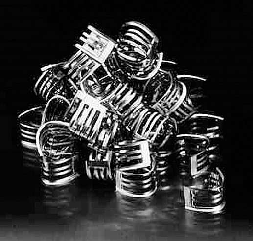
Metallic packing
High-performance random tower packing
- Provides greater capacity and efficiency than fractionation trays and other random packings
- Exhibits roughly 40% lower pressure drop than equal-sized pall rings
- Minimizes liquid residence time through low liquid holdup
- This type of packing is ideal in a wide range of mass transfer services. It is used extensively in distillation towers from deep vacuum towers where its low pressure drop is crucial, to high-pressure towers where its capacity easily surpasses that of trays

Random tower packing
High-strength pall ring & raschig rings
- Physical strength without thickness and weight
- Economically priced
- Our high-strength pall ring combines flared ends with a latch that holds the ring seams together for uniform closure and added strength for use in beds up to 50 feet (15m). The high-strength pall ring is currently available in a 2-in. (50mm) size in a broad range of metals

Rasching ring
6.4.4 Packed tower internals
The proper selection and design of packed tower distributors, collectors, supports, and other column internals are essential for optimum packing performance.
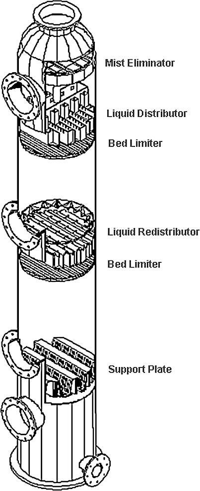
Packed tower internals
Support plates
They provide structural support for packing. A well-designed packing support plate provides structural support for the tower packing. Weight loads associated with installation, liquid holdup during operation and the potential for scaling or buildup of solids enter into the design considerations. The support plate must minimize resistance to the flows of rising vapor and down coming liquid. Additionally the support plate must be easy to install.

Support plates
Liquid distributors
Proper liquid distribution represents one of the most important aspects of packed tower design. For critical applications in large towers, we recommend the trough distributor.

Liquid distributors
Liquid re-distributors
Optimum tower performance depends upon uniform liquid distribution though multiple packed beds. Re-distributors accomplish this task by accumulating the liquid leaving an upper bed and distributing it in a uniform patter over a lower bed.
Collecting trays are required if more than one liquid is used in a multiple bed packed tower. The collecting tray collects and removes liquid from the tower while permitting vapor to move upward though the successive packed bed.

Liquid Re-distributors
Collecting trays
Optimum tower performance depends upon uniform liquid distribution though multiple packed beds. Re-distributors accomplish this task by accumulating the liquid leaving an upper bed and distributing it in a uniform patter over a lower bed.
Collecting trays are required if more than one liquid is used in a multiple bed packed tower. The collecting tray collects and removes liquid from the tower while permitting vapor to move upward though the successive packed bed.

Collecting trays
Bed limiters
Bed limiters hold packings in their proper location. The gas velocity and the packing material determine whether a given tower requires a bed limiter. High gas velocities can lift the packing, dislocating it into the liquid distributor or beyond. This adversely impacts the performance of the liquid distributor and the efficiency of the tower.

Bed limiters
Mist eliminators
Carry over of liquid particulate matter by gas or vapor is generally termed as ‘Entrainment’, which is commonly encountered in Gas-Liquid separations
Mist eliminators are a highly efficient, low cost means of removing entrained liquid droplets from gas and vapor streams.

Mist eliminators
6.4.5 Structured packing
In general, the deciding issue for structured packing is more a question of vapor density and liquid density rather than system pressure.
Three criteria control the selection of structured packing:
- Liquid load
- Vapor density
- Liquid-to-vapor density ratio
For distillation systems, the vapor density and the liquid-to-vapor density ratio are strongly linked. The lower the vapor density, the better-structured packing performs compared to other devices. The higher the vapor density, the better trays or random packing performs compared to structured packing.

Structured packing
6.5 Types of distillation
6.5.1 Fractional distillation
If a portion of the distillate is returned from the condenser and made to drip down through a long column onto a series of plates, and if the vapor rises on its way to the condenser is made to bubble through this liquid at each plate, the vapor and liquid will interact so that some of the water in the vapor condenses and some of the alcohol in the liquid vaporizes. The interaction at each plate is thus equivalent to a re-distillation, and by building a column with a sufficient number of plates, 95 percent alcohol can be obtained in a single operation. Moreover, by feeding the original 10 percent alcohol solution gradually at a point in the middle of the column, virtually all the alcohol may be stripped from the water as it descends to the lowest plate, so that no alcohol need be wasted.
This process, known as rectification, fractionation, or fractional distillation, is common in industrial usage, not only for simple mixtures of two components (such as alcohol and water in fermentation products, or oxygen and nitrogen in liquid air) but also for highly complex mixtures such as those found in coal tar and petroleum.

Fractionating column
The only disadvantage of fractional distillation is that a large fraction (as much as one-half) of the condensed distillate must be refluxed, or returned to the top of the tower and eventually boiled again, and more heat must therefore be supplied. On the other hand, the continuous operation made possible by fractionation allows great heating economies, because the outgoing distillate may be used to preheat the incoming feed.
When the mixture consists of many components, they are drawn off at different points along the tower. Industrial distillation towers for petroleum often have over 100 plates, with as many as ten different fractions being drawn off at suitable points. Towers with more than 500 plates have been used for the separation of isotopes by distillation.
6.5.2 Steam distillation
If two insoluble liquids are heated, each is unaffected by the presence of the other (as long as they are agitated so that the lighter liquid does not form an impenetrable layer over the heavier), and vaporizes to an extent determined only by its own volatility. Such a mixture, therefore, always boils at a temperature lower than that of either constituent; and the percentage of each constituent in the vapor depends only on its vapor pressure at this temperature. This principle may be applied to substances that would be damaged by overheating if distilled in the usual fashion.

Steam distillation unit
6.5.3 Vacuum distillation
Another method of distilling substances at temperatures below their normal boiling points is to partially evacuate the still. Thus, aniline may be distilled at 100° C (212° F) by removing 93 percent of the air from the still. This method is as effective as steam distillation, but somewhat more expensive. The greater the degree of vacuum, the lower is the distillation temperature. If the distillation is carried on in a practically perfect vacuum, the process is called molecular distillation. This process is regularly used industrially for the purification of vitamins and certain other unstable products. The substance is placed on a plate in an evacuated space and heated. The condenser is a cold plate, placed as close to the first as possible. Most of the material passes across the space between the two plates, and therefore very little is lost.
The VDU (Vacuum Distillation Unit) takes the residuum from the ADU (Atmospheric Distillation Unit) and separates the heavier products such as vacuum gas oil, vacuum distillate, slop wax, and residue.
6.5.4 Centrifugal molecular distillation
If a tall column of mixed gases is sealed and placed upright, a partial separation of the gases takes place because of gravity. In a high-speed centrifuge or an instrument called a vortex, the forces separating the lighter and heavier components from each other are thousands of times greater than gravity, making the separation more efficient. For example, separation of gaseous uranium hex fluoride, UF6, into molecules containing two different uranium isotopes, uranium-235 and uranium-238, may be effected by means of centrifugal molecular distillation.
6.5.5 Destructive distillation
If a substance is heated to a high temperature and decomposed into several valuable products, and these products are separated by fractionation in the same operation, the process is called destructive distillation. The important applications of this process are the destructive distillation of coal for coke, tar, gas, and ammonia, and the destructive distillation of wood for charcoal, acetic acid, acetone, and wood alcohol. The latter process has been largely displaced by synthetic processes for making the various by-products. The cracking of petroleum is similar to destructive distillation.
6.5.6 Flash distillation
Flash Distillation is a process by which a liquid-liquid mixture is separated by vaporizing one of the components in a tank (‘flash drum’). After leaving the tank, the vaporized component is then condensed, leaving two separate components. The components of the liquid-liquid mixture are separated based on volatility
The liquid-liquid mixture (‘the feed stream’) is pumped through a heater where the temperature is increased. The pressure is then reduced as the feed flows through a valve and into the flash drum. The reduced pressure in conjunction with the increased temperature causes a vaporization of the more volatile component. In the flash drum, the two phases are given a large enough volume to separate. The liquid and vapor phases flow out of the bottom and top, respectively.
Flash distillation should be used when separating two liquid components with significant differences in boiling points. The amount of separation in flash distillation is limited, which makes it a poor choice when a high purity is desired. The mechanism of separation for flash distillation is heat, so consideration should be taken when components are heat sensitive. This process occur when the product enter into a vessel.
Figure 6.22 shows the elements of a flash-distillation plant. Feed is pumped by pump through a heater, and the pressure is reduced through valve. An intimate mixture of vapor and liquid enters the vapor separator, in which sufficient time is allowed for the vapor and liquid portions to separate. Because of the intimacy of contact of liquid and vapor before separation, the separated streams are in equilibrium.

Flash distillation unit
Examples and applications
- Petroleum Processing - Flash Distillation is used to separate petroleum in a process called ‘cracking’. The products produced include: gasoline, kerosene, lubricating oils, asphalt, etc
- Alcohol Production - Flash Distillation is used to separate the ethanol (vapor phase) from the water (liquid phase) in order to form a more concentrated product
- Desalination of Water - Flash Distillation is used to purify salt water by boiling off pure water, leaving salt behind in the remaining water
- Perfume Spray - Flash Distillation is used to extract the essential oils of flowers and cedar to make perfume
Multi-stage flash distillation
Multi-Stage Flash (MSF) is the most commonly used process for seawater desalination. A MSF facility is typically located so that it uses steam from a nearby electricity generation facility. Seawater is heated in a ‘brine heater’ and proceeds to another receptacle, called a stage, where it immediately boils (flash) due in part to the ambient pressure. The steam yielded is the condensed on heat exchanger tubes that in turn heat up the incoming water, thereby decreasing the amount of thermal energy needed to heat the Feed water.
It is an advantage to perform flash-distillation in several steps. This is called multi-stage flash evaporation or MSF for short. This is where the preheated liquid passes through a series of stages or chambers with each successive stage at a lower vapor pressure so some of the liquid will flash at each stage.
Flash distillation begins when the salt water enters a bundle of tubes which are located in the vapor space of the preheat chamber. The water then flows into a heater consisting of a bundle of tubes, which are heated externally by steam. Here, the water is heated to 100 degrees C, but it does not boil because the pressure is above 1 atm. The hot seawater then enters a flash chamber, which is kept under reduced pressure. The vapors, which are flashed off, are then condensed on the tubes carrying the incoming flow of cold seawater. The distillate and the remaining salt water are then restored to atmospheric pressure by pumps. Condensing the water by heat exchange with the incoming flow in one of the economical advantages of this process.
The multiple stage evaporators is able to produce more distillate per unit of heating steam because the flashing occurs in more than one stage since the flashed vapors are used to heat the incoming water.

Multiple flash units
6.5.7 Osmosis distillation
Osmosis denotes the movement of water down a concentration gradient. Water moves from an area of high concentration to an area of lower concentration. Rather than using concentration gradients as a driving force, osmotic distillation uses the differences in vapor pressures of the contacting liquid phases. This allows actual separation of water from other components without the other components ‘following’ the water as it moves.
This is particularly useful in concentrating food and pharmaceutical products that are sensitive to elevated temperatures. A liquid phase with one or more volatile components is separated from a salt solution by a non-wetting polymer membrane. The membrane is typically made of non-polar polymers such as polyethylene, polypropylene, or PTFE.
This membrane functions as a vapor barrier between the liquid phases. The salt solution is usually composed of sodium or calcium chloride. Figure 6.24 shows the interface arrangement used in osmotic distillation.

Interface arrangement of osmotic distillation
Mechanism
Water moves across the Osmotic Distillation (OD) membrane by evaporating, diffusing through the pores, and condensing on the other side of the pores. The liquid is prohibited from entering the pores by membrane design. The membrane is designed such that the liquids cannot exceed the capillary forces required to enter the pores. Design factors include surface tension, contact angle, capillary pressure, and pore radius. The heat of vaporization is supplied by conduction or convection from the upstream liquid through the membrane. The temperature gradient across the membrane is typically less than 2 0C making the process nearly isothermal.
Figure below shows a typical setup used in osmotic distillation.

Typical setup used in osmotic distillation
Osmotic distillation provides a means of purifying heat sensitive substances including pharmaceuticals and biological products.
6.6 Sublimation
If a solid substance is distilled, passing directly into the vapor phase and back into the solid state without a liquid being formed at any time, the process is called sublimation. Sublimation does not differ from distillation in any important respect, except that special care must be taken to prevent the solid from clogging the apparatus. Rectification of such materials is impossible. Iodine is purified by sublimation.
6.7 Leaching
Removal of materials by dissolving them away from solids is called leaching. Leaching has been used to separate metals from their ores and to extract sugar from sugar beets. Environmental engineers have become concerned with leaching more recently because of the multitude of dumps and landfills that contain hazardous and toxic wastes. Sometimes the natural breakdown of a toxic chemical results in another chemical that is even more toxic. Rain that passes through these materials enters ground water, lakes, streams, wells, ponds, and the like.
Although many toxic materials have low solubility in water, the concentrations that are deemed hazardous are also very low. Furthermore, many toxic compounds are accumulated by living cells and can be more concentrated inside than outside a cell. This is why long-term exposure is a serious problem; encountering a low concentration of a toxic material a few times may not be dangerous, but having it in your drinking water day after day and year after year can be deadly.
For single stage leaching, two steps are involved:
- Contact of solid and solvent for transfer of solute to solvent
- Separation of resulting solution from the residual solid
The EXTRACT is the solvent phase.
The RAFFINATE is the solid material and its adhering solution.
The solute in the raffinate is in both dissolved and undissolved forms.

Terminology
The main theory of leaching neglects mechanisms for holding the material on the solid. Although adsorption and ion exchange can bind materials tightly to solids, we will simplify the analysis and consider only dissolving a soluble constituent away from an insoluble solid. An example is removing salt from sand by extraction with water.
Countercurrent stage wise processes are frequently used in industrial leaching because they can deliver the highest possible concentration in the extract and can minimize the amount of solvent needed. The solvent phase becomes concentrated as it contacts in a stage wise fashion the increasingly solute-rich solid. The raffinate becomes less concentrated in soluble material as it moves toward the fresh solvent stage.

Leaching stages
6.7.1 Heap leaching
Heap leaching is a countercurrent process where the solid is in a stationary heap and the solvent percolates through the solid. An example is a dump or landfill. This leaching is essentially countercurrent. In industrial leaching, solvent and solid are mixed, allowed to approach equilibrium, and the two phases are separated. Liquid and solids move counter currently to the adjacent stages. The solvent phase, called the extract, becomes more concentrated as it contacts in stage wise fashion the increasingly solute-rich solid. The raffinate becomes less concentrated in soluble material as it moves toward the fresh solvent phase.

Heap leaching
Heap leaching is also used in recovering metals from their ores. Bacterial leaching is first used to oxidize sulphide minerals. Cyanide solution is then used to leach the metals from the mineral heap.

Metal recovery through Heap Leaching
6.7.2 Leaching for remediation
Leaching has potential for clean up of toxic waste sites, but there must be no dispersal of the contaminants to adjacent areas. If the toxic material is soluble in water, it may already be dispersed by the percolation of rainwater or by flow of groundwater.
The penetration of wastes down into the soil has been modeled by several groups. A representative paper by Janssen, et al., (1990) considers the migration of radioisotopes deposited on soil by fallout from a nuclear accident.
Movement depends on convection with the solvent, diffusion, and exchange with the soil solids. This is much more complicated than batch or countercurrent leaching where we neglected any binding of the solute because the equilibria are complex and the motion is in three dimensions. Problems of this type require considering many elements that interact. The term for this approach is finite element analysis, and linear algebra with matrices aids the solutions.
If contaminated soil were flushed by pumping water through it, the pumped water under pressure would escape to the surroundings. This is unacceptable because the toxic wastes would be diluted to make treatment more difficult and dispersed to make collection more costly. A well to withdraw contaminated water should be in the region of highest concentration of contaminant. The following sketch shows a pumping scheme that might be acceptable for leaching with water pumped at the periphery to create higher pressure to prevent flow out of the site. The leachate is treated (a bioprocess is shown in this figure) and recycled. The above-ground treatment is tricky because the concentration of toxic material will usually be low. Both chemical and biological processes have troubles in dealing with dilute streams.
Toxic and hazardous wastes are often organic chemicals with poor water solubility. The most efficient way to extract them from soil would be to use organic solvents. However, adding solvents to soil would make the problem worse even if the solvents were not toxic. The expense would be unreasonable, and organics would represent very high BOD. One solvent that has been proposed is supercritical carbon dioxide in which many organic compounds are highly soluble. Lost solvent would merely escape to the air. The drawback is that the temperature and pressure to keep the carbon dioxide in its supercritical state would be a severe engineering challenge. There are only a few industrial extractions with supercritical fluids, and the technology is considered advanced and costly.
Volatile compounds can be extracted from soil simply by flushing with a gas. One attractive method for removing organic solvents from soil is aeration. The removal is somewhat slow but cost effective. Venting the spent air adds to air pollution, so some treatment is advisable. The air could be sent to a combustion unit where the contaminants burn along with the fuel. Another option is adsorption on activated carbon. The organic contaminants are burned off when the carbon is roasted to regenerate it for reuse.

Remediation
There are many different types of equipment used for leaching. Most of these pieces of equipment fall into one of two categories:
- Whether the leaching is taking place via percolation or by dispersed-solids, there are three important factors that aid in leaching: temperature, contact time/area, and solvent selection. Temperature is adjusted to optimize solubility and mass transfer
- Liquid-to-solid contact is essential for the extraction to take place and maximize contact area per unit volume reduces equipment size. Solvent selection plays an important role in solubilities as well as the separation steps that follow leaching. Nearly all leaching equipment employs some type of agitation to aid in mass transfer and to ensure proper mixing
6.7.3 Leaching by percolation
Stationary solid-bed leaching is done in a tank with a perforated false bottom to support the solids and permit drainage of the solvent. Solids are loaded into the tank, sprayed with solvent until their Solute content is reduced to the economical minimum, and excavated. In some cases the rate of solution is so rapid that one passage of solvent through the material is sufficient, but countercurrent flow of solvent through a battery of tanks is more common. In this method, fresh solvent is fed to the tanks in series and is finally withdrawn from the tank that has been freshly charged. Such a series of tanks is called an extraction battery. The solid in any one tank is stationary until it is completely extracted. The piping is arranged so that fresh solvent can be introduced to any tank and strong solution withdrawn from any tank, making it possible to charge and discharge one tank at a time. The other tanks in the battery are kept in countercurrent operation by advancing the inlet and draw-off tanks one at a time as the material is charged and removed. Such a process is sometimes called a shanks process.
In some solid-bed leaching, the solvent is volatile, necessitating the use of closed vessels operated under pressure. Pressure is also needed to force solvent through beds of some less permeable solids. A series of such pressure tanks operated with countercurrent solvent flow is known as a diffusion battery.
6.7.4 Moving bed leaching
The Bollman extractor shown in figure 6.31 consists of a U-shaped screw conveyor with a separate helix in each section. The helices turn at different speeds to give considerable compaction of the solids in the horizontal section. Solids are fed to one leg of the U and fresh solvent to the other to give countercurrent flow.

Bollman extractor
6.7.5 Counter current leaching plant
In leaching, soluble material is dissolved from its mixture with an inert solid by means of a liquid solvent. A diagrammatic flow sheet of a typical countercurrent leaching plant is shown in figure 6.32. It consists of a series of units, in each of which the solid from the previous unit is mixed with the liquid from the succeeding unit and the mixture allowed to settle. The solid is then transferred to the next succeeding unit, and the liquid to the previous unit. As the liquid flows from unit to unit, it becomes enriched in solute, and as the solid flows from unit to unit in the reverse direction, it becomes impoverished in solute. The solid discharged from one end of the system is well extracted, and the solution leaving at the other end is strong in solute. The thoroughness of the extraction depends on the amount of solvent and the number of units. In principle, the unextracted solute can be reduced to any desired amount if enough solvent and a sufficient number of units are used.
Any suitable mixer and settler can be chosen for the individual units in a countercurrent leaching system. In those shown in figure 6.32 mixing occurs in launders A and in the tops of the tanks, rakes B move solids to the discharge, and slurry pumps C move slurry from tank to tank.

Counter current leaching plant
6.8 Centrifugal extractors
The dispersion and separation of the phases may be greatly accelerated by centrifugal force, and several commercial extractors make use of this. In the Podbielniak extractor, a perforated spiral ribbon inside a heavy metal casing is wound around a hollow horizontal shaft through which the liquids enter and leave. Light liquid is pumped to the outside of the spiral at a pressure between 3 and 12 atm to overcome the centrifugal force; heavy liquid is pumped to the center.

Centrifugal extractor
The liquids flow counter currently through the passage formed by the ribbon and the casing walls. Heavy liquid moves outward along the outer face of the spiral; light liquid is forced by displacement to flow inward along the inner face. The high shear at the liquid-liquid interface results in rapid mass transfer.
6.9 Gas absorption
The application of gas absorption techniques in chemical engineering process operations has expanded rapidly in recent years, particularly in the fields of exhaust gas scrubbers and the recovery of hydrogen chloride, hydrogen bromide and oxides of sulfur. In many instances, the efficient recovery of these materials is dictated by economic operating requirements.
The absorption process relies on the ability of a liquid phase to hold within its body relatively large quantities of a gaseous or vapor component. This ability makes it possible to remove one or more selected components from a gas stream by contacting with and absorbing into a suitable liquid.
Whatever type of absorption process is being considered, in order to achieve efficient gas absorption, the gas must be brought into intimate contact with the liquid phase. The equipment must therefore provide a large interfacial area for this contact to occur. In order to achieve this, several basic designs have evolved.
6.9.1 Falling film absorbers
Failing film absorption, units are very similar in construction to vertically mounted shell and tube heat exchangers. The absorbent flows down the walls of the tubes co-currently with the gas stream. Liquid distribution is provided by a weir arrangement at the top of the tube bundle. The shell side of the unit contains the cooling water.

Falling film evaporator
The system consists essentially of a vertical shell-and-tube exchanger known as the cooler-absorber, a packed tail gas scrubber and interconnecting piping. The gas to be absorbed enters the system through an inlet at the upper end of the heat exchanger and flows down inside the parallel tubes with the flow of absorbing liquid. Unabsorbed gas passes through a riser to the bottom of the tail gas scrubber. The absorbing liquid is fed through an inlet at the top of the tail gas scrubber and falls over the packing countercurrent to the rising gas. The acid leaving the tower is fed to the top tube sheet of the heat exchanger. In this way, the heat exchanger works as a number of water cooled, wet-wall columns in parallel. The falling film absorber is provided with weirs and an elaborate distribution system to effect an equal flow of liquid and gas to each tube.
The greatest virtue of the Falling Film Absorber is its capability to produce strong acid without detectable vent losses. The Falling Film Absorber can be used for the absorption of HCI, HBr, SO, , NH, etc.
6.9.2 Exhaust gas scrubber
The exhaust gas scrubber represents one of the simplest forms of the absorption process and is used where concentrations in the feed gas to the column are low and the component cannot be economically recovered. As the liquid to gas ratio is normally high, any heat of solution generated in the process is taken up by the liquid phase. Heat exchangers to cool the product stream are, therefore, not normally required.
Absorption in this type of operation can also be combined with a neutralization process, for example, the use of an alkaline solution in an acid gas scrubber, as shown below.

Exhaust scrubber
6.9.3 Pure gas absorber (constant feed rate)
As the feed gas is pure, or contaminated with air and water vapor only. any vapors generated by the heat of solution during the absorption process are condensed within the column itself and are returned with the make up water to the packed section. Any non-condensable leave the column by a vent at the top. The product is cooled by the lower heat exchanger before it leaves the column.
Note: The acid strength control unit is only applicable in the case of HCI absorption.

Pure gas absorber
6.10 Cooling towers
Cooling towers are a very important part of many chemical plants. They represent a relatively inexpensive and dependable means of removing low-grade heat from cooling water The make-up water source is used to replenish water lost to evaporation. Hot water from heat exchangers is sent to the cooling tower. The water exits the cooling tower and is sent back to the exchangers or to other units for further cooling.
6.10.1 Natural draft
Cooling towers fall into two main sub-divisions: natural draft and mechanical draft. Natural draft designs use very large concrete chimneys to introduce air through the media. Due to the tremendous size of these towers (500 ft high and 400 ft in diameter at the base) they are generally used for water flow rates above 200,000 gal/min.

Natural draft tower
The green flow paths show how the warm water leaves the plant proper, is pumped to the natural draft-cooling tower and is distributed. The cooled water, including makeup from the lake to account for evaporation losses to the atmosphere, is returned to the condenser.
6.10.2 Mechanical draft
Mechanical draft towers use one or more fans to move large quantities of air through the tower. They are divided into two classes:
- Forced draft cooling towers
- Induced draft cooling towers
The airflow in either class may be cross flow or counterflow with respect to the falling water. Crossflow indicates that the airflow is horizontal in the filled portion of the tower while counterflow means the airflow is in the opposite direction of the falling water.
The counterflow tower occupies less floor space than a crossflow tower but is taller for a given capacity. The principle advantages of the crossflow tower are the low-pressure drop in relation to its capacity and lower fan power requirement leading to lower energy costs.
All mechanical towers must be located so that the discharge air diffuses freely without recirculating through the tower, and so that air intakes are not restricted. Cooling towers should be located as near as possible to the refrigeration systems they serve, but should never be located below them so as to allow the condenser water to drain out of the system through the tower basin when the system is shut down.
Forced draft cooling towers
The forced draft tower, shown in figure 6.38 has the fan, basin, and piping located within the tower structure. In this model, the fan is located at the base. There are no louvred exterior walls. Instead, the structural steel or wood framing is covered with paneling made of aluminum, galvanized steel, or asbestos cement boards

Forced draft tower
During operation, the fan forces air at a low velocity horizontally through the packing and then vertically against the downward flow of the water that occurs on either side of the fan. Water entrained in the air is removed by the drift eliminators located at the top of the tower. Vibration and noise are minimal since the rotating equipment is built on a solid foundation. The fans handle mostly dry air, greatly reducing erosion and water condensation problems
Induced draft cooling towers
The induced draft tower illustrated in figure 6.39 has one or more fans, located at the top of the tower, that draw air upwards against the downward flow of water passing around the wooden decking or packing. Since the airflow is counter to the water flow, the coolest water at the bottom is in contact with the driest air while the warmest water at the top is in contact with the moist air, resulting in increased heat transfer efficiency.

Counterflow induced draft cooling tower
The fans at the top discharge the hot, moisture laden air upward and away from the air entering at the bottom of the tower, thus preventing any recirculation of warm air. Warm water from the building enters the distribution system located just under the drift eliminators. The fans and their drive are mounted on the top deck.
A schematic drawing of another type of induced draft tower, called the crossflow is shown in figure 6.40. Crossflow towers provide horizontal airflow as the water falls through the packing. Single and double airflow designs are constructed to suit the job location and operating conditions.

Crossflow tower design
The fans, located at the top, draw air through cells or packing that are connected to a suction chamber partitioned midway beneath each fan. The water falls from the distribution system in a cascade of small drops over the packing and across the horizontal flow of air. The total travel path of the air is longer and there is less resistance to air flow than in the counterflow design.
A newer type of induced draft cooling tower design is illustrated in Fig.6.40. The tower consists of a venturi-shaped chamber, a spray manifold, and a sump. Neither fill nor fan are required in this tower.

Venturi tower
The water to be cooled is injected at the narrow end of the venturi by spray nozzles, inducing a large airflow into the tower, which mixes intimately with the fine water spray. Heat transfer by evaporation of a small part of the water takes place while the remaining water drops in temperature. The cooled water falls into the sump and from there flows to the suction of the cooling water circulating pump. The air containing the water vapor leaves the tower via the eliminators and is discharged upward through a cowl.
The advantages of this tower are its quietness of operation due to the absence of any moving parts and their associated noise and vibration problems, the elimination of the need for electrical connections, starters, etc., the elimination of fill, and the reduced maintenance requirements. A cross-sectional view of this tower is shown in figure 6.42.

Cross section venturi tower
6.11 Desiccant dehumidifiers
There are four typical equipment configurations for desiccant dehumidifiers:
- Liquid spray-tower
- Solid packed tower
- Solid granular based
- Rotating horizontal bed
- Multiple vertical bed
- Fluted media based
6.11.1 Solid granular based
Rotating horizontal bed
In this device, dry, granular desiccant is held in a flat, segmented rotary bed that rotates continuously between the process and reactivation airstreams. As the bed rotates through the process air, the desiccant adsorbs moisture. Then the bed rotates into the reactivation airstream, which heats the desiccant, raising its vapor pressure and releasing the moisture to the air.
The process and reactivation air heats and cools the desiccant to drive the adsorption-desorption cycle. The moisture is removed through a process of continuous physical adsorption on a continuous basis (both, counter flow and parallel flow options are available).
The adsorption of moisture and reactivation of desiccant take place continuously and simultaneously without any cross mixing of the process and reactivation air streams.

Rotating horizontal bed
To increase capacity, the manufacturer can either increase the diameter of the rotating bed to hold more desiccant, or increase the number of beds stacked on top of one another. Both options are not practical if very large volumes of air need to be dehumidified. If the desiccant is evenly loaded through the trays, the rotating horizontal bed provides a constant outlet moisture level, and a high airflow capacity can be achieved in less floor space than with dual-tower unit. The rotating horizontal bed design offers a low first cost. The design is simple, compact and easy to produce as well as install and maintain.
Modular Vertical Bed (MVB)
The Modular Vertical Bed (MVB) design is a ‘fairly new’ but ‘proven’ concept with the combined better features of packed tower and rotating horizontal bed designs in an arrangement that is well suited to atmospheric pressure dehumidification applications, and yet can achieve very low dew points. The single or double tower is replaced by a circular carrousel with eight or more vertical beds (towers) that rotate, by means of a drive system, between the process and reactivation air streams.
This design can achieve low dew points because leakage between process and reactivation air circuits is almost negligible. Also because the beds are separate and sealed from one another, the pressure difference between process and reactivation is not so critical; so airstreams can be arranged in the more efficient counter-flow pattern for better heat and mass transfer. Like the rotating bed, the ratcheting, semi-continuous reactivation of the desiccant provides a relatively constant outlet air moisture condition on the process side, reducing the ‘saw tooth’ effect that can occur in packed tower units.

Moving vertical bed
The ‘MVB’ design allows for low replacement cost of desiccants as well as large savings in energy and performance improvements at low dew points, especially if the equipment incorporates a heat pipe heat exchanger in the regeneration air circuit.
6.11.2 Fluted media based dehumidifiers
Another dehumidifier design uses a rotating fluted wheel/rotor to present the desiccant to the process and reactivation airstreams. This is sometimes called a fluted media/honeycomb type dehumidifier. The desiccant is impregnated/ synthesised on ‘honeycomb’ like corrugated rotor. The principle of operation is the same as the solid desiccant (granular) based system.
The process air flows through the flutes formed by the corrugations, and the desiccant in the structure adsorbs the moisture from the air. The rotating desiccant bed picks up moisture, and well before ‘saturation’ the rotor/wheel rotates into the reactivation segment where it is heated to drive off the moisture.
The fluted design has its own advantages as it is comparatively light weight and has a smaller foot print. The fluted design is the preferred option where space is a limitation and there is a leeway to sacrifice ‘performance’ slightly. One has to also keep in mind the higher replacement cost of the rotor compared to the desiccant in the granular systems.

Fluted media
6.12 Adsorptions systems
The important commercial adsorption configurations are:
- Pressure swing adsorption systems
- Vacuum swing adsorption
- Liquid phase carbon adsorption
- Vapor phase carbon adsorption
6.12.1 Pressure swing adsorption (PSA) systems
The simplified diagram above outlines the major components in a PSA. The key to selective gas separation is the choice of sieve material packed in the dual containers or vessels.

PSA
For nitrogen service, a Carbon Molecular Sieve (CMS) is typically used. The physical pore size of the sieve enables smaller O2 molecules to be adsorbed on the surface of the sieve. The rate of loading is also faster for the oxygen (kinetic separation effect), so the surface of the sieve adsorbs most of the O2, and the nitrogen molecules are allowed to pass by the sieve as the product gas. The higher the pressure, the greater adsorption capacity of the CMS.
Before the CMS reaches equilibrium, when N2 will also be adsorbed, the pressurized gas in the first vessel is vented to the second vessel that is at lower pressure. Residual O2 in the first vessel is then ‘desorbed’ from the CMS and vented at atmospheric pressure. All required valving operations are done automatically by carefully calculated timing cycles controlled by a PLC.
The ‘product’ N2 gas from both adsorption towers is collected in a common receiver vessel. N2 purities of 99.99% are possible by the PSA process.
For oxygen service, the CMS is replaced with specialized zeolites to preferentially adsorb nitrogen, thereby delivering O2 at approximately 95% purity with the same process diagram shown above.
6.12.2 Vacuum swing adsorption
The simplified diagram above outlines the major components in a VSA. The key to selective gas separation is the choice of sieve material packed in the dual containers or vessels. The process is quite similar to Pressure Swing Adsorption systems, except that differential pressures take place at lower absolute pressures.

VSA
For oxygen service, specially treated zeolites are used as the adsorption sieve. Even at low pressure, nitrogen is preferentially adsorbed to the surface of the zeolite, allowing enriched oxygen to be produced. The rate of loading is faster for the nitrogen (kinetic separation effect), so the surface of the sieve adsorbs most of the N2. The produced oxygen also contains unadsorbed argon and residual N2, so that attainable O2 purities range between 90 to 95%.
The VSA process begins by charging the first vessel with low-pressure air, initiating the N2 adsorption process, similar to a sponge soaking up water. Before the zeolite reaches equilibrium, when O2 will also be adsorbed, the pressurized gas in the first vessel is vented to the second vessel that is at lower pressure (vacuum). Residual N2 in the first vessel is then ‘desorbed’ from the zeolite and vented at atmospheric pressure. All required valuing operations are done automatically by carefully calculated timing cycles controlled by a PLC.
For nitrogen service, the zeolite is replaced by carbon molecular sieve to preferentially adsorb oxygen, thereby delivering N2 at purities up to 99.99% with the same process diagram shown above.
6.12.3 Liquid phase carbon adsorption systems
The process flow diagram illustrates a municipal water treatment plant that is used for the removal of taste and odour compounds. Water is pumped from the river into a flotation unit, which is used for the removal of suspended solids such as algae and particulate material. Dissolved air is injected under pressure into the basin through special nozzles. This creates microbubbles, which become attached to the suspended solids, causing them to float. The result is a layer of suspended solids on the surface of the water, which is removed using a mechanical skimming technique

CAS
6.12.4 Vapor phase carbon adsorption system
The process flow diagram illustrates a dry adsorption system, used to clean flue gas from a large municipal waste incineration plant. The flue gases are cooled in economisers to the correct temperature for efficient reaction. Hydrated lime is injected for the control of acid gases together with powdered activated carbon , which is used for the removal of gaseous heavy metals and dioxins. The flue gases react with these materials in the ducts and fabric filters, where collection takes place together with the fly ash.

VCAS
6.13 Drying
6.13.1 Drying of solids
These are the most frequent applications of fluid beds. Different process systems are applied depending upon product, volatiles, operational safety and environmental requirements.
Open system
Featuring atmospheric air in a once-through system where water is to be removed. Normally a push-pull system is used to balance the pressure to be slightly negative in the free board of the fluid bed. Depending upon the product and available heat source, direct or indirect heating may be applied. The exhaust air is cleaned by e.g. bag filter, cyclone with or without wet scrubber.
In cases where products pose a dust explosion risk, open cycle systems feature pressure shock resistant components or alternatively semi-closed cycle, self-inertizing layouts can be considered.

Open system
Closed cycle system
This features drying in an inert gas atmosphere (usually nitrogen) recycling within the system. It must be used for drying feedstocks containing organic volatiles or where the product must not contact oxygen during drying. Closed cycle systems are gastight, and addition of inert gas is controlled by monitoring the oxygen content of the drying gas and the system pressure, which is kept positive. The evaporated volatiles are recovered in a condenser.

Closed system
Batch fluid bed systems
Batch fluid bed processing allows several process steps (mixing, agglomerating, drying and cooling) to be carried out in a single unit. The batch process assures uniformity of all products within a batch and allows every unit of final product to be traced to a given batch run.

Fluid bed system
6.14 Drying equipment
6.14.1 Tray dryers
The dryers consist of a cabinet containing trays, which is connected to a source of air heated by gas, diesel or bio-mass such as rice husk. The air temperature is usually controlled by a thermostat which is normally set between 50 and70 O C. The air renters the bottom of the chamber below the trays and then rises, through the trays of food being dried, and exits from an opening in the top of the chamber. In the IT systems the trays are designed to force the air to follow a longer zig-zag route which increases the air/food contact time and thus efficiency. This system also reduces back pressure which means that cheaper, smaller fans can be used.

Tray dryer Cross section
There are three basic types of tray dryer cabinets Batch, Semi-Continuous and Cross Flow Dryers. Batch Cabinets are the simplest and cheapest to construct. The cabinet is a simple large wooden box fitted with internal runners to support the trays of food being processed. The trays are loaded into the chamber, the doors closed and heated air is blown through the stack of trays until all the product is dry. Clearly, as the hot air enters below the bottom tray, this tray will dry first. The last tray to dry is the one at the top of the chamber.

Tray dryer
The advantages and disadvantages of this system are:
- Simple, low cost chamber
- Low labor costs – simply load and then unload
- A tendency to over-dry the lower trays
- Low efficiency, in terms of furl consumption, in the later stages of drying when most of the
- Trays are dry
6.14.2 Screen conveyor dryers
One of the older and gentler technologies associated with drying is conveyor drying. Conveyor dryers - also referred to as band or apron dryers - are used extensively throughout a variety of industries. They have found a particular niche in the food industry for products such as pet food, fruits and vegetables, extruded snacks and cereals.
The feed to a conveyor dryer needs to be reasonably well formed and robust to:
- Allow a dimensionally stable and porous bed to be formed
- Prevent the formation of fines within the dryer, which can result in carryover to the heating system as most of these dryers operate on a recycle basis
- Inhibiting the blocking of perforations on the belt
This feed will take on the form of large granules, agglomerates, pellets, preformed or extruded products (pressure agglomerates), small solid particles, large solid particles and applicable agricultural products.
Conveyor dryers process at rates that are consistent with their specific applications but are on the lower end of throughput capacities in the assortment of dryer technology. This relatively low rate is a limitation primarily imposed by physical logistics and capital cost. Conveyor dryers principally are through-the-bed dryers although cross-flow and radiant units are used occasionally for specific products. Units can be directly or indirectly heated using burners (gas, LFO or HFO) or coils (steam, electrical heater banks or thermal oil).

Conveyor dryer
The principle of a conveyor dryer is simple: Feed is placed on a perforated belt and hot gas is passed through the belt and feed. This principle remains the same as the technology develops. The feed is metered on the belt to create a bed, the formation of which is fundamental to the efficiency of the drying process. The belt moves and a seal between the static (stationary) and dynamic (moving) components contains the bed, preventing short-circuiting of the carrier gas. The heat source, belt, drives, feeding mechanism and primary gas movers are installed in a frame, and the entire system is insulated. Entry doors along the length and ends of the dryer provide access to the moving components. Fines collection and gas ducting (primary and recirculation) are designed for each application. It is a simple principle but with a rather complicated mechanical design
6.14.3 Tower dryers
A tower dryer contains a series of circular trays mounted one above the other on a central rotating shaft. Solid feed dropped on the topmost tray is exposed to a stream of hot air or gas, which passes across the tray. The solid is then scraped off and dropped to the tray below. It travels in this way through the dryer, discharging as dry product from the bottom of the tower. The flow of solids and gas may be either parallel or countercurrent.

Tower dryer
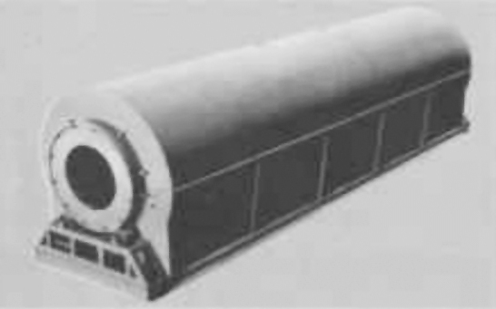
6.14.4 Rotary dryers
Rotary dryers potentially represent the oldest continuous and undoubtedly the most common high volume dryer used in industry, and it has evolved more adaptations of the technology than any other dryer classification. Rotary dryer technology includes direct rotary cascade dryers, indirect (steam) tube rotary dryers, multipass rotary dryers, rotary tube furnace dryers, and rotary louver dryers. Drum dryers are sometimes referred to as ‘rotary’ drum dryers and paddle dryers are sometimes referred to as ‘rotary’ paddle dryers, but the technology behind these dryers is distinctly different and will not be included in this family.

Rotary dryer
In simple terms, a rotary dryer introduces wet feed into one end of a tube and a hot gas into the same or opposite end. The tube rotates and the hot gases and feed are intimately mixed while being transported down the tube, producing a dry product and a wet exhaust.
Because the heat transfer and presentation aspects of the different variations of these dryers are not the same for each configuration, these will be discussed individually. All rotary dryers have the feed materials passing through a rotating cylinder termed a drum.
The drum is mounted to large steel rings, termed riding rings, or tires that are supported on fixed trunnion roller assemblies. The rotation is achieved by either a direct drive or chain drive, which require a girth gear or sprocket gear, respectively, on the drum. The drum expands at operating temperature, so it is important that only one side, usually the feed end, be constrained with thrust rollers in the longitudinal direction.

Rotary drum
Spiral flights quickly move the material out of the feed section. Lifting flights elevate the material to produce a curtain. The drum is supported by a riding ring.
The drum normally is inclined down from feed to discharge at an angle of 1 to 4 degrees. The initial section of the drum has helical screw or spiral flights to rapidly move the material out of the feed section. Material moves from one end of the dryer to the other by the motion of the material falling ‘forward’ or rolling ‘downhill’ due to the angle of inclination of the drum as well as other dynamics associated with the angle of inclination and the rotation of the drum. Frequently, there also is a discharge spiral section to prevent blocking of the dryer discharge. Rotary dryers can process extremely high volumes of product: The drums can have diameters ranging from less than half a yard for laboratory units to in excess of 13’ (4 m) for large-scale applications.
Direct rotary cascade dryers
The most common type of rotary dryer, direct rotary cascade dryers have internal lifters or flights to elevate the feed and drop it in a curtain from the top to the bottom, cascading along the length of the dryer hence the name rotary cascade dryers. These flights need to be carefully designed to prevent cross-sectional asymmetry of the curtain. The flights are arranged in repeating patterns, and the dryer should have several rows of distinctively designed flights that are indexed and offset to form numerous simultaneous curtains along the drum length.

Rotary cascade dryer
Direct rotary cascade dryers have internal lifters or flights to elevate the feed and drop it in a curtain from the top to the bottom, cascading along the length of the dryer. The carrier stream (hot gas) may be co- or countercurrent with the primary flow being through the ‘bed’ or curtain, and, in this instance, multiple curtains in the longitudinal direction. As you can imagine, the formation of each curtain is intermittent. Therefore the design should allow for successive curtains to be formed in advance, promoting a continuous exposure of the feed to the carrier. Secondary crossflow occurs on the surface of the bed material on the bottom of the drum.
Rotary steam tube dryers
Rotary steam tube dryers operate in a similar fashion to conventional rotary cascade dryers with the exception that the heat transfer is indirect (principally conductive) with the material cascading through a rotating nest of tubes that are internally heated by steam or other thermal transfer fluid. The lifters, if used, are on the peripheral circumference of the drum. Otherwise, the tubes actually act as the lifters or conveying medium that elevate the feed to the top of the drum and release it to contact and tumble through the tube bundle directly. Many have spirals installed to assist in moving the materials forward. Only evolved vapors are exhausted from the drum, requiring a lower volume of air for the process.
Rotary louver dryers
This type of rotary dryer has the feed materials supported and moving over a set of louvers mounted to an external rotating drum. The hot gas is introduced into a tapered bustle below the louver ring. The air passes through the louvers and the product (through the bed) before being exhausted from the dryer in a co-current or countercurrent flow. The drum rotation causes the material to roll and mix, providing intimate contact with the drying gas. There is a certain amount of fluidization that occurs in a rotary louver dryer, leading to this technology being thought of as a combined fluid-bed rotary dryer. The technology provides a very gentle method of handling the material and is especially well suited for fragile and crystalline materials.

Rotary louver dryer
Rotary tube furnace dryers
An indirect dryer that allows a high degree of temperature control, a Rotary Tube Furnace (RTF) dryer consists of a muffle furnace with a steel drum passing through it. Tumbling or rolling flights rather than the lifting flights such as those in the cascade rotary dryer are fitted to the inside of the drum. In operation, the particles are exposed to the drum surface, which is heated from the outside by a suitable heat source such as gas burners or electric elements. The internal flights tumble and mix the product, constantly exposing new surfaces to the heated drum surface. In addition, there is a high degree of conduction between the product particles to enhance operation efficiency.
In all rotary dryers the speed of advancement of the material and hence its retention time in the dryer is determined by the rotational speed of the drum as well as its angle of inclination. By varying these parameters, the residence time can be controlled accurately. The amount of material in the drum at any one time the drum fill is relatively low as a percentage of the cross-sectional area or total volume of the drum. They are typically of the order of 8 to 15 percent of the total volume of the drum.

Rotary Tube Furnace Dryers
Rotary dryers are continuous processing machines that can effectively process feeds that are classified as powders, granules, nonfriable agglomerates and large solid particles. Some -- the direct cascade and tube furnace, for example -- are able to cope with wide variations in the feed such as particle size and moisture. Depending on the configuration of the particular dryer, the feed and carrier inlets, discharges (or both) need to be well sealed to prevent the introduction of cold air into the system or the expulsion of hot, dust-laden air to the atmosphere. They operate at varying feed rates from several pounds to hundreds of tons per hour.
6.14.5 Screw-conveyor dryers
A screw-conveyor dryer is a continuous indirect-heat dryer, consisting essentially of a horizontal screw conveyor (or paddle conveyor) enclosed in a cylindrical jacketed shell. Solid fed in one end is conveyed slowly through the heated zone and discharges from the other end. The vapor evolved is withdrawn through pipes set in the roof of the shell. The shell is 3 to 24 in. (75 to 600mm) in diameter and up to 20ft (6m) along; when more length is required, several conveyors are set one above another. Coolant in the jacket lowers the temperature of the dried solids before they are discharged.
The rate of rotation of the conveyor is slow, from 2 to 30 r/min. Heat-transfer coefficients are based on the entire inner surface of the shell, even though the shell runs only 10 to 60 percent full. The coefficient depends on the loading in the shell and on the conveyor speed. It ranges, for many solids, between 3 and 10 Btu/ft2-h-oF (17 and 57 W/m2-oC).
Screw-conveyor dryers handle solids that are too fine and too sticky for rotary dryers. They are completely enclosed and permit recovery of solvent vapors with little or no dilution by air. When provided with appropriate feeders, they can be operated under moderate vacuum. Thus they are adaptable to the continuous removal and recovery of volatile solvents from solvent-wet solids, such as spent meal from leaching operations. For this reason they are sometimes known as desolventizers.
Screw-conveyor dryers
6.14.6 Fluid-bed dryers
Fluid bed dryers are found throughout all industries, from heavy mining through food, fine chemicals and pharmaceuticals. They provide an effective method of drying relatively free-flowing particles with a reasonably narrow particle size distribution. The feed may take the form of powders, granules, crystals, pre-forms and nonfriable agglomerates. Technology for processing of liquids in fluid bed systems using host media does exist, but it will not be discussed.
Fluid bed dryers can process a wide variation of feed rates, from a few pounds to several hundred tons per hour. Three principle types of fluid bed dryers exist. The first type is referred to as a static fluid bed because the dryer remains stationary during operation. Static fluid bed dryers can be continuous or batch operation and may be round or rectangular. The second type of fluid bed dryer is a vibrating fluid bed dryer, where the body of the dryer vibrates or oscillates, assisting the movement of material through the unit. Vibrating fluid bed dryers are almost exclusively rectangular in shape. The third type of fluid bed dryer fluidizes the material from the top by means of tubes that deflect on a solid pan lifting the material on the deflected airflow. This technology will not be discussed in this column. Fluid bed dryers may use a direct, indirect or combination heat source to provide the energy required to achieve drying.
Fluid bed types
Fluid bed processors may be configured for either continuous or batch operation.
Transport of the solids through the fluid bed may be achieved either by the fluidization alone or a combination of fluidization and vibration.
The flow of gas relative to the solids is characterized either as cross flow in a single tier fluid bed or as cross/counter-current in a multi-tier fluid bed.
There are two types of basic fluid bed designs according to the solids flow pattern in the dryer.
Continuous back mix flow
The continuous back-mix flow design for feeds that require a degree of drying before fluidization is established.
These are applied for feeds that are non-fluidizable in their original state, but become fluidizable after a short time in the dryer, e.g. after removal of surface volatiles from the particles.
The condition of the fluidizing material is kept well below this fluidization point. Proper fluidization is obtained by distributing the feed over the bed surface and designing the fluid bed to allow total solids mixing (back-mix flow) within its confines. The product temperature and moisture are uniform throughout the fluidized layer. Heating surfaces immersed in the fluidized layer improve the thermal efficiency and perfomance of this system. Back-mix fluid beds of both rectangular and circular designs are available
Back mix flow
Plug flow design
The plug flow design for feeds that are directly fluidizable on entering the fluid bed.
These are applied for feeds that are directly fluidizable. Plug flow of solids is obtained by designing the fluid bed with baffles to limit solids mixing in the horizontal direction. Thereby the residence time distribution of the solids becomes narrow. Plug flow fluid beds of either rectangular or circular designs are especially used for removal of bound volatiles or for heating and cooling. The volatile content and temperature vary uniformly as solids pass through the bed, and the plug flow enables the solids to come close to equilibrium with the incoming gas.

Plug mix flow
Plug flow may be achieved in different ways depending on the shape and size of the bed.
- In rectangular beds, baffles are often arranged to create an alternating flow of solids from side to side
- In circular beds, baffles are spiral
- In relatively small circular beds with high powder layers, baffles are radial
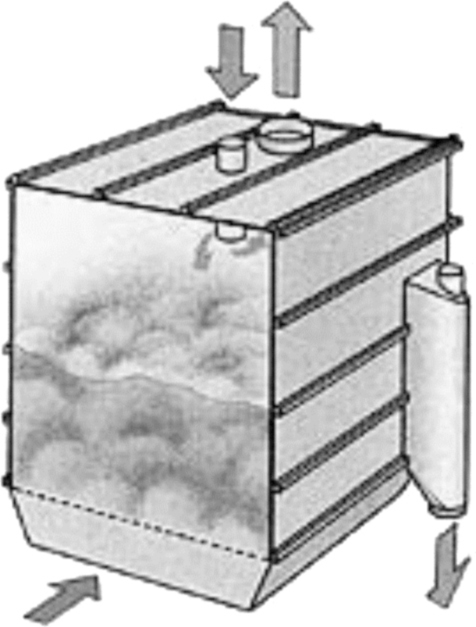
Vibrating fluid beds
This design, is basically of the plug flow type. It is especially applied for drying and cooling products that fluidize poorly due to a broad particle size distribution, highly irregular particle shape, or require relatively low fluidization velocities to prevent attrition. It operates with a shallow powder layer of less than 200 mm. This gives a much lower product residence time per unit bed area than non-vibrating beds which can have powder layers up to 1500 mm.
These fluidizers incorporate pressure shock resistance and sanitary features if clean operation is required.

Vibrating fluid bed
Contact fluidizers
This is a rectangular fluid bed dryer incorporating back-mix and plug flow sections. A rotary distributor disperses the wet feed evenly over the back-mix section equipped with contact heating surfaces immersed in the fluidized layer.
The heating surfaces provide a significant portion of the required energy, and therefore, it is possible to reduce both the temperature and the flow of gas through the system. This is particularly important for heat sensitive products.
Subsequent plug flow sections are used for postdrying and cooling, if required.
Advantages of the Contact Fluidizer - compared to fluid beds without heating surfaces, two-stage flash/fluid bed dryers, or rotary dryers - include its compact design, high thermal efficiency, and low gas throughput.
Multi-tier fluid beds
These fluid beds consist of two or more stacked fluid beds. The upper tier (back-mix or plug flow) is for predrying and the lower tier (plug flow) for postdrying. The drying gas travels counter-current to the solids. The gas leaving the lower tier contains sensible heat, which is transferred to the upper tier. Furthermore, each fluid bed may be provided with immersed heating surfaces. These designs result in a low gas throughput and high thermal efficiency which are of great importance in closed cycle drying systems.

Multi-tier fluid bed
6.14.7 Flash dryers
There are four factors, which influence the evaporation of moisture during flash drying.
Figure 6.67, illustrates the system consisting of Heater, Conditioner and the Disintegrator along with a Cyclone.

Flash dryer
- Moisture dispersion
Free flowing materials with moisture distributed over a relatively large surface area can be flash dried with little or no conditioning. Filter cakes and feeds with the consistency of mud can be conditioned for better drying by mixing them with previously dried material - Particle size
Shape and size are related to moisture dispersion. The smaller the particle, the more rapid the moisture removal. Thus, operations requiring simultaneous grinding and drying particularly adaptable to the flash drying process - Temperature differential
High inlet temperatures are utilized in flash drying. This is possible because the drying takes place so quickly. The material is dried and removed from the hot gas stream before it ever reaches the wet bulb temperature of the gas. It is common to use inlet design temperature of 650°C for highly combustible products such as sewage sludge and spent grain - Agitation
Rapid drying is also the result of maximum agitation or turbulence of the particles. High gas velocities in the flash dryer accomplish this
6.14.8 Spray dryers
Spray drying is one of the oldest forms of drying and one of the few technologies available for the conversion of a liquid, slurry or low viscosity paste to a dry solid (free-flowing powder) in one unit operation. Spray dryers are found in almost every industry, including mining and minerals, pharmaceuticals and detergents, paint and pigments, and food and dairy. They can dry at rates from several pounds to several tons per hour but become expensive to operate at the higher rates.

Spray atomizer
Spray dryers or towers, as they are sometimes called, atomize or spray the feed material into the drying chamber in fine droplets. They are continuous processing machines that come in a range of configurations. Traditional vertical configurations are broadly grouped into two categories depending on the method of introducing the feed. The first of these, tall-form dryers, use nozzles to atomize the feed. They are so termed due to the relatively narrow spray angle of the nozzle and the relative velocity of the droplets, requiring a tall drying chamber with a proportionally small diameter to provide sufficient residence time to achieve drying. The second group, which are shorter and fatter, use rotary disk atomizers (also referred to as centrifugal atomizers) to generate the spray. The angle of the rotary atomizer spray is flat with a wide spray pattern, requiring a large diameter tower that is relatively short. Other spray dryer configurations include box spray dryers, which rely on the same operating principles but extract the product from the bottom of the dryer housing by means of a conveyor, and pulse-combustion spray dryers. Rotary atomizer spray is flat with a wide spray pattern, and it requires a short, large-diameter tower.
The feed liquid is pumped into the atomization system that, by virtue of its technology, either will immediately atomize the feed to a spray of droplets (pressure nozzles) or feed the rotary disk that will atomize the product (rotary atomizer). Pressure nozzles rely on the pump supply pressure (or fluid such as compressed air in a two-fluid nozzle) to effect the atomization. Therefore, in tall-form dryers, high-pressure pumps or high pressure fluids usually are required for operation. A low-pressure pump is required for rotary atomizers to overcome the head associated with the change in elevation required to supply the feed from the ground to the top of the tower. The disk of the atomizer is driven at a high rate of revolution by an electric motor. The feed is metered onto the disk that creates a spray of material into the drying chamber by centrifugal forces.
The technology behind atomization, be it from pressure nozzles or rotary atomizers, is a science in itself. Without going into great detail, I can tell you that by adjusting parameters and components of the atomizer in conjunction with dryer configuration, you can effectively produce a final product that will meet specific product characteristics such as rehydration, moisture content, particle size and bulk density. Atomizer selection is based on the requirements of the final product, and each type of atomizer offers unique advantages outside of a common broad regime.
All atomizers (pressure or rotary) create a fine spray of feed into the tower’s drying chamber. In so doing, the surface area of the feed has been increased dramatically to allow for intimate contact between the carrier and product. In the pulse combustion dryer, the burner is used to both atomize the product and introduce the carrier into the system.
Spray dryers can be co-current, counter-current or fountain flow, depending on the material’s sensitivity to temperature, desired dry product characteristics and selection of the system. They may be direct or indirect and can use a variety of heat sources. In co-current systems, the hot gas (carrier) is introduced with the feed at the top of the tower and extracted at the discharge cone through an extraction duct. With counter-current systems, the carrier is introduced by means of a bustle above the dryer cone and exhausted from the top of the tower. With fountain flow, the product is sprayed vertically upward and changes direction within the drying chamber.
Pulse drying first was introduced as a commercially available method of drying in the early ‘80s. This method of spray drying uses a pulse combustion burner to both atomize the product and introduce the carrier into the system. This design obviates the requirement for both insulated hot gas ducting and high-pressure pumps and nozzles or rotary disk atomizers. The principle of atomization relies on the burner producing a high frequency combustion/detonation within the burner. The so-formed gases are channeled into a resonating chamber, where the frequency of the wave so formed is amplified. This wave atomizes the feed, which is metered in at low pressure, and entrains the particles in the hot gases, which are diluted by a secondary process air makeup within the burner/nozzle assembly to the required process temperature. The remainder of the dryer is identical to a tall-form co-current spray dryer.

Spray dryer
Spray dryers typically employ induced-draft fans to extract the moisture-laden air from the system. In some instances, special fans are installed to achieve dryer-specific operations such as air sweeps.
Due to the fine product that is produced on spray dryers, they inherently require dedicated dust-collection systems such as cyclones, bag houses, scrubbers and electrostatic precipitators.
Spray dryers are controlled by programmable logic controllers (PLCs) or solid-state controllers. In spray drying systems, the exhaust air temperature or humidity provides an input signal that, by way of a setpoint, will modulate the energy supplied to the process. Mechanically, these dryers are relatively low maintenance units. They can be fabricated from materials ranging from basic carbon steel to sophisticated duplex stainless steels. These dryers must be fully insulated to allow energy-efficient operation. Tall-from dryers have a pump and exhaust fan that require differing amounts of maintenance depending on the service, environment and abrasion characteristics of the product. Likewise, nozzles may wear -- specifically, the orifice plates -- and may require frequent replacement due to the wear adversely affecting the spray pattern. Dryers using rotary atomizers can become somewhat of a maintenance challenge, having to lift relatively large motors and gearboxes to the top of the tower for replacement. Facilities to assist in the maintenance and replacement of rotary atomizers can be designed into the system.
Tall-form dryers use nozzles to atomize the feed. The relatively narrow spray angle of the nozzle and relative velocity of the droplets require a tall drying chamber with a proportionally small diameter to provide sufficient residence time to achieve drying.
Spray dryers do have limitations. They are extremely energy intensive and have a correspondingly high operating cost. This is due to the fact that considerably more moisture is being thermally evaporated from the feed than in most other types of dryers. It is more expensive to thermally evaporate moisture than mechanically dewatering. Many spray dryers have problems relating to product buildup on the dryer walls. In some instances, this buildup is so significant it adds additional load to the tower, stressing the structure.
Spray dryers have a unique position in the arena of thermal drying. There is no other high volume method of producing a free-flowing powder from a liquid in one step. They offer unique, unmatched versatility in the production of powders and can control the powder characteristics to a specified requirement.
Conventional two-stage dryer
This is a spray dryer layout featuring either a rotary atomizer or spray nozzle atomizer. Powder discharged from the drying chamber can be further dried and cooled in a vibrating fluid bed. This two-stage drying concept achieves better overall heat economy and is suitable for many food and dairy products. When non-agglomerated powders of non-fat products are dried, a pneumatic transport system can replace the fluid bed.

Two-stage dryer
Compact dryer
This is a space saving spray dryer with integrated fluid bed. Atomization is created by either a rotary atomizer or spray nozzle atomizer. The location of the fluid bed within the drying chamber permits drying at lower temperature levels, resulting in higher thermal efficiencies and cooler conditions for handling powders. The plant can be equipped with pneumatic transport system for many powders or with an external vibrating fluid bed for agglomerated powders.

Compact dryer
Tall form dryer
A tower spray dryer with a top mounted nozzle assembly featuring a fines return capability. The atomized droplets dry while gently falling down the tower. Further drying and cooling are carried out in a vibrating fluid bed located under the tower. The tall form dryer is suited for both non-fat and fat-containing products, producing non-agglomerated and agglomerated free-flowing powders.

Tall dryer
Multi-stage dryer
This is a spray dryer with an integrated fluid bed. The spray is created by a spray nozzle atomizer. Operational flexibility enables production of a wide range of physical properties. The process produces non-dusty, free flowing agglomerated powders with high flavor retention. It operates with low outlet temperatures, achieving high thermal efficiency. Dry ingredients for additional flavor or nutrient fortification can be added within the system to further promote capabilities and improve formulation efficiencies. This design concept is successful for drying high fats, hygroscopic, and sticky products that are difficult to handle in more conventional designs.

Multi stage dryer
6.14.9 Thin-film dryers
Thin film evaporators, thin film dryers and short path evaporators all work on basis of processing a product in a thin turbulent film. The heart of the thin film technology is the rotor which creates the thin product film. The product is picked up by the rotor blades and immediately formed into a thin turbulent film on the heat transfer surface (Figure 6.74). Due to the low film thickness (from 0,5 mm) the heat and mass transfer rates are significantly improved compared to non agitated heat transfer equipment. The volatile component of the feed stock is therefore very quickly evaporated. For this reason the thin film technology has become a generally recognised and accepted solution for the most difficult and demanding processing problems in the areas of distillation, concentration, degassing, drying, cooling and reaction. Without thin film technology the efficient processing of many products from the chemical, pharmaceutical, food and polymer industries be either extremely difficult or impossible.
Commonly thin film equipment is jacketed on the thermal surface. Mostly a double jacket is used for steam or liquid heat transfer agents. When working with high pressure, half coils welded to the inner shell are required.

Thin film dryer
Features of inductive heating
Thin film equipment with an inductive heating system is designed without any jacket in the evaporation zone. Inductive heating is generated in the inner shell by wrap-around copper coils. Inductive heating permits temperatures of up to 500 °C for any type of thin film equipment, either of cylindrical or conical design of the evaporation zone.
Thin film technology is commonly the last stage of a thermal separation process requiring the highest temperature. The possibility of avoiding installing a special hot oil system for this last stage can often prove an economically interesting alternative for the following reasons:
- High operational safety (no rotating parts, e. g. pumps, no oil leakages)
- Easy erection (control cabinet only)
- Smaller space requirements (no hot-oil unit, no piping)
- Reduced inspection and testing by minimising the number of pressure retaining parts
- High specific heat transfer rates
- Short heat up time
- High overall thermal efficiency due to reduced radiation from a hot oil unit and associated pipe work
- Fine temperature control
- Safety requirements for hot oil are not required
6.14.10 Drum dryers
A drum dryer consists of one or more heated metal rolls on the outside of which a thin layer of liquid is evaporated to dryness. Dried solid is scraped off the rolls as they slowly revolve.
Continuous operation permits mass:
- Production
- Adjustment of temperature, volume, rotation speed and humidity of drying
- Easily carried out to meet the required conditions
- Handles bulky products and materials while assisting to break up the mass
- Agglomerations
- Simple construction, easy operation and maintenance

Drum dryer
No comments:
Post a Comment